مهندسان جوش ( welding engineers )
جوشکاری یا عیبمهندسان جوش ( welding engineers )
جوشکاری یا عیبدرباره من
 با سلام خدمت تمام بازدید کنندگان
من بهزاد بهرامی بیرگانی دانشجوی
دانشگاه آزاد واحد شهر مجلسی
رشته مهندسی تکنولورژی جوشکاری
این وبلاگ صرفآ جهت افزایش اطلاعات
شما در این رشته جوشکاری جمع آوری
شده شما میتوانید با ثبت نظرات خود
من را آگاه کرده تا مطالب مورد نظر شما
را در صورت امکان در وبلاگ قرار داده تا
مورد استفاده بیشتر شما قرار گیرد
با تشکر از مهندس اسحق محمدی
برای کمک و رفع مشکلات شما به گروه
ما پیوست امیدوارم همیشه موفق باشد
بدورود .
با تشکر از یاسین غلامی زاده
مهندس و بازرس جوش
با ما در تماس باشید
ایمیل : welding.engineers@yahoo.com
مدیریت وبلاگ : بهزاد بهرامی بیرگانی
ادامه...
با سلام خدمت تمام بازدید کنندگان
من بهزاد بهرامی بیرگانی دانشجوی
دانشگاه آزاد واحد شهر مجلسی
رشته مهندسی تکنولورژی جوشکاری
این وبلاگ صرفآ جهت افزایش اطلاعات
شما در این رشته جوشکاری جمع آوری
شده شما میتوانید با ثبت نظرات خود
من را آگاه کرده تا مطالب مورد نظر شما
را در صورت امکان در وبلاگ قرار داده تا
مورد استفاده بیشتر شما قرار گیرد
با تشکر از مهندس اسحق محمدی
برای کمک و رفع مشکلات شما به گروه
ما پیوست امیدوارم همیشه موفق باشد
بدورود .
با تشکر از یاسین غلامی زاده
مهندس و بازرس جوش
با ما در تماس باشید
ایمیل : welding.engineers@yahoo.com
مدیریت وبلاگ : بهزاد بهرامی بیرگانی
ادامه...
فر آیندهای جوشکاری با پرتو الکترونی

جوشکاری بروش الکترونی
بعد از اینکه در اواخر دهه 1950 جوشکاری EBW برای اولین بار به عنوان اولین پروسه جوشکاری استفاده شد، این فرآیند یک مقبولیت گسترده در صنعت بدست آورد. در ابتدا در صنایع هستهای بکار برده شد، و بعد مختصراً در صنایع فضایی و هواپیمایی، به کار گماشته شد، به سرعت تشخیص داده شد که فرآیند دارای ظرفیت لازم برای افزایش دادن کیفیت و قابلیت اعتماد قطعات بسیار حساس و بحرانی که در این صنایع استفاده شده است را دارد. فرآیند همچنین هزینه های ساخت را نیز کاهش داد. در طول این دورة ابتدایی کاربرد تجاری، فرآیند اکیداً برای عملیات در محفظة خلاء محدود شد. هر چند که سیستمی به زودی توسعه یافت که خلاء بالا تنها در قسمت تولید اشعه لازم بود. این سیستم اجازة انتخاب جوشکاری در یک محیط نیمه خلاء یا در یک محیط بدون خلاء را میدهد. این پیشرفت منجر بر مقبولیت آن توسط سازندگان خودروهای تجاری و سازندگان کالاهای معرفی شده در نتیجه جوشکاری EBW در رنج گستردهای از صنایع در کل جهان استفاده شده است. از اواخر دهة 1960 فرآیند هر دو تای جوش کم عمق و جوش بسیار عمیق تک پاسه را با کمترین مقدار اعوجاج حرارتی در قطعه کار را فراهم کرد.
ادامه مطلب ...
جوشکاری پرتوالکترونی
فرایند جوشکاری پرتوالکترونی (EBW) فرایندی است که ذوب و اتصال فلزات در آن توسط حرارت حاصل از یک پرتوالکترونی صورت میگیرد. همان گونه که در شکل الف نشان داده شده است، کاتد تفنگ پرتوالکترونی، یک فیلمان (افروزه) با بار منفی است. هنگامی که این فیلمان تا بیش از دمای نشر گرمایونی آن گرم شود، از خود الکترون ساطع میکند. این الکترونها، توسط میدان الکتریکی بین الکترود شبکه با بار منفی (که کمی پایینتر از کاتد قرار گرفته است) و آند شتابدار میشوند. سپس از سوراخ روی آند عبور کرده و توسط یک سیمپیچ الکترومغناطیسی بر روی یک نقطه بر سطح قطعه کار متمرکز میشوند. جریان پرتو در روش EBW بین 50 تا A1000 و ولتاژ شتاب دهنده بین 30 تا KV175 متغیر است. یک پرتو الکترونی با شدت بسیار زیاد قادر است تا فلز را تبخیر کرده و یک سوراخ در حین جوشکاری در قطعه ایجاد کند که همان سوراخ کلیدی بوده و در شکل الف نشان داده شده است. شکل نشان میدهد که با کاهش فشار محیط، قطر پرتو کاهش مییابد. علت این امر آن است که الکترونها در اثر برخورد با مولکلوهای هوا پراکنده میشوند و بنابراین کاهش فشار محیط سبب کاهش پراکندگی آنها خواهد شد. این امر دلیل اصلی انجام فرایند EBW در محفظه خلاء میباشد.
ادامه مطلب ...
Welding Steel Alloys
Welding Steel Alloys
Steel Alloys can be divided into five groups
Steels are readily available in various product forms. To establish a proper welding procedure it is necessary to know the material properties of the steel being welded. The American Iron and Steel Institute defines carbon steel as follows: |
|
Steel is considered to be carbon steel when no minimum content is specified or required for chromium, cobalt, columbium [niobium], molybdenum, nickel, titanium, tungsten, vanadium or zirconium, or any other element to be added to obtain a desired alloying effect; when the specified minimum for copper does not exceed 0.40 per cent; or when the maximum content specified for any of the following elements does not exceed the percentages noted: manganese 1.65, silicon 0.60, copper 0.60. Carbon steels are normally classified as shown below.
Low-carbon steels contain up to 0.30 weight percent C. The largest category of this class of steel is flat-rolled products (sheet or strip) usually in the cold-rolled and annealed condition. The carbon content for these high-formability steels is very low, less than 0.10 weight percent C, with up to 0.4 weight percent Mn. For rolled steel structural plates and sections, the carbon content may be increased to approximately 0.30 weight percent, with higher manganese up to 1.5 weight percent.
Medium-carbon steels are similar to low-carbon steels except that the carbon ranges from 0.30 to 0.60 weight percent and the manganese from 0.60 to 1.65 weight percent. Increasing the carbon content to approximately 0.5 weight percent with an accompanying increase in manganese allows medium-carbon steels to be used in the quenched and tempered condition.
High-carbon steels contain from 0.60 to 1.00 weight percent C with manganese contents ranging from 0.30 to 0.90 weight percent.
High-strength low-alloy (HSLA) steels, or microalloyed steels, are designed to provide better mechanical properties than conventional carbon steels. They are designed to meet specific mechanical properties rather than a chemical composition. The chemical composition of a specific HSLA steel may vary for different product thickness to meet mechanical property requirements. The HSLA steels have low carbon contents (0.50 to ~0.25 weight percent C) in order to produce adequate formability and weldability, and they have manganese contents up to 2.0 weight percent. Small quantities of chromium, nickel, molybdenum, copper, nitrogen, vanadium, niobium, titanium, and zirconium are used in various combinations.
Below are some typical welding considerations when welding carbon and low alloy steels
- Carbon Equivalent of the Steel
- Weld Cooling Rates
- Solidification Cracking
- Reheat Cracking
- Lamellar Tearing
- Hydrogen Cracking
If your company is experiencing these or other welding problems you can retain AMC to improve your weld processing. Hire AMC to act as your welding specialist.
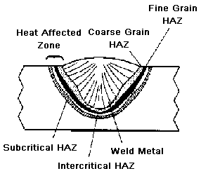
DISTORTION
DISTORTION
Welding involves highly localized heating of the metal being joined together. The temperature distribution in the weldment is therefore nonuniform. Normally, the weld metal and the heat affected zone (HAZ) are at temperatures substantially above that of the unaffected base metal. Upon cooling, the weld pool solidifies and shrinks, exerting stresses on the surrounding weld metal and HAZ.
If the stresses produced from thermal expansion and contraction exceed the yield strength of the parent metal, localized plastic deformation of the metal occurs. Plastic deformation results in lasting change in the component dimensions and distorts the structure. This causes distortion of weldments.
Several types of distortion are listed below:
- Longitudinal shrinkage
- Transverse shrinkage
- Angular distortion
- Bowing
- Buckling
- Twisting
Factors affecting distortion
If a component were uniformly heated and cooled distortion would be minimized. However, welding locally heats a component and the adjacent cold metal restrains the heated material. This generates stresses greater than yield stress causing permanent distortion of the component. Some of the factors affecting the distortion are listed below:
- Amount of restraint
- Welding procedure
- Parent metal properties
- Weld joint design
- Part fit up
Restraint can be used to minimize distortion. Components welded without any external restraint are free to move or distort in response to stresses from welding. It is not unusual for many shops to clamp or restrain components to be welded in some manner to prevent movement and distortion. This restraint does result in higher residual stresses in the components.
Welding procedure impacts the amount of distortion primarily due to the amount of the heat input produced. The welder has little control on the heat input specified in a welding procedure. This does not prevent the welder from trying to minimize distortion. While the welder needs to provide adequate weld metal, the welder should not needlessly increase the total weld metal volume added to a weldment.
Parent metal properties, which have an effect on distortion, are coefficient of thermal expansion and specific heat of the material. The coefficient of thermal expansion of the metal affects the degree of thermal expansion and contraction and the associated stresses that result from the welding process. This in turn determines the amount of distortion in a component.
Weld joint design will effect the amount of distortion in a weldment. Both butt and fillet joints may experience distortion. However, distortion is easier to minimize in butt joints.
Part fit up should be consistent to fabricate foreseeable and uniform shrinkage. Weld joints should be adequately and consistently tacked to minimize movement between the parts being joined by welding.
If your company is experiencing these or other welding problems you can engage AMC to reduce your welding distortion. Hire AMC to act as your welding specialist.
جوشکاری سازه آیین نامه ها Structural Welding Codes
سازه آیین نامه ها چندین سازه جوش آیین نامه ها وجود دارد. این صفحه وب را فراهم رئوس مطالب جوشکاری سازه کود. مثالهای نمونه از این زیر لیست شده اند عبارتند از :
فولاد (AWS D1.1)
آلومینیوم (AWS D1.2)
آرماتور فلزی (AWS D1.4)
فولاد ضد زنگ (AWS D1.6)
بررسی اجمالی
کدهای جوشکاری سازه پوشش جنبه های مختلف برای ساخت و احداث سازه های جوش داده شده. در حالی که از تغییرات در قوانین جزایی را از زمان به زمان ارائه میدهد که در اینجا ارائه یک مرور کلی از اطلاعات موجود در کد وجود دارد.
برای مقایسه کدهای جوش سازه جامع تر از بخش نهم تحت فشار بویلر و مخازن ASME کد (BPVC) ، از مسائل از قبیل طراحی و ساخت هستند ، در بخش دیگری از ASME BPVC خطاب. برخی از نمونه های مورد نیاز جوشکاری خطاب توسط آیین نامه ها سازه جوش عبارتند از :
طراحی اتصالات جوش داده شده
الزامات مورد نیاز برای جوش مشخصات روش کار (WPS)
پرسنل مورد نیاز برای جوشکاری عملکرد تحصیلی مدرک
ساخت مورد نیاز
بازرسی
طراحی جوش
مهندسان به طور معمول اتصالات جوش داده شده و مطابق با الزامات آن شناسایی شده در جوشکاری کد طرح. کد آدرس جنبه های مختلف جوشکاری. برخی از مسائل جوشکاری زیر مشخص شده اند
welds شیاردار
welds گچ بری
طول جوش
کامل نفوذ مشترک
نفوذ ناقص مشترک
شلپ شلپ کردن مفاصل
اندازه جوش
فاصله جوش
انتقال قدرت
سازههای ثابت و ادواری بارگذاری
مدرک
مشخصات روش جوشکاری (WPS) و عملکرد تحصیلی مدرک جوش پرسنل مورد نیاز است. مدرک تحصیلی را پوشش میدهد جنبههای مختلف مربوط به تولید welds. برخی از این آیتم ها در زیر آورده شده عبارتند از :
فرآیند جوش (SMAW ، GMAW ، FCAW ، GTAW ، ص و غیره)
فلز پایه
فلز پر کننده
قبلا گرم و درجه حرارت Interpass
شدت جریان برق
ولتاژ
سرعت سفر
گاز محافظ
ضخامت
موقعیت جوش
پشتیبانی
مشخصات مورد نیاز برای روش جوشکاری و جوشکاری پرسنل عملکرد تحصیلی مدرک در کدهای شناسایی می شوند.
ساخت
ساخت و نصب قطعات و سازه های جوش داده شده در کد شده اند. برخی از اقلام تحت پوشش کد زیر فهرست شده اند
فلز پایه
مواد مصرفی جوشکاری
قبلا گرم و درجه حرارت Interpass
تسکین استرس حرارتی
پشتوانه ، پشتوانه گاز ، یا درج
محیط زیست جوش
تطابق طراحی
آمادگی و پایه فلزی
ابعاد و تلرانس
مشخصات جوش
تعمیرات
بازرسی
مدارک مورد نیاز برای بازرس و مسئولیت ، معیارهای پذیرش برای discontinuities و روشهایی برای آزمایش غیرمخرب (غیر مخرب) را در کد شناسایی می شوند. برخی از موارد شناسایی شده در کد زیر آمده است :
بازرس
مواد
WPS
تجهیزات
جوشکار مدرک
Welds
سوابق
ضوابط پذیرش
البدل ضوابط پذیرش
تست مایع نافذ
تست ذرات مغناطیسی
رادیوگرافی بازرسی
التراسونیک بازرسی
اگر شرکت شما است با این مسائل را تجربه و یا مشکلات جوشکاری دیگر شما می توانید AMC پردازش جوش خود را بهبود بخشید را حفظ کنید. استخدام مشاور ما در عمل به عنوان متخصص جوش دهید
Structural Welding Codes
There are several Structural Welding Codes. This web page provides an outline of the Structural Welding Codes. Typical examples of these are listed below:
Steel (AWS D1.1)
Aluminum (AWS D1.2)
Reinforcing Steel (AWS D1.4)
Stainless Steel (AWS D1.6)
Overview
The Structural welding Codes cover various aspects for fabricating and erecting welded structures. While there are changes to the Codes from time to time the outlines here provide an overview of the information in the codes.
For comparison the Structural Welding Codes are more comprehensive than Section IX of the ASME Boiler and Pressure Vessel Code (BPVC), as issues such as design and fabrication are addressed in other sections of the ASME BPVC. Some examples of welding requirements addressed by the Structural Welding Codes include:
Design of welded connections
Requirements for Welding Procedure Specifications (WPS)
Requirements for Welding Personnel Performance Qualification
Fabrication Requirements
Inspection
Weld Design
Engineers typically design welded connections in accordance with the requirements identified in the welding code. The codes address various aspects of the weld. Some of the weld issues specified are listed below
Groove welds
Fillet welds
Weld length
Complete joint penetration
Partial joint penetration
Lap joints
Weld size
Weld spacing
Transitions
Static and cyclical loading
Qualification
Welding Procedure Specifications (WPS) and Welding Personnel Performance Qualification are required. The qualification covers various aspects concerning the production of welds. Some of these items are listed below:
Welding Process (SMAW, GMAW, FCAW, GTAW, SAW etc.)
Base metal
Filler metal
Preheat and Interpass temperature
Amperage
Voltage
Travel speed
Shielding gas
Thickness
Backing
Requirements for Welding procedure Specifications and Welding Personnel Performance Qualification are identified in the Codes.
Fabrication
Fabrication and erection of welded assemblies and structures are detailed in the code. Some of the items covered by the code are listed below
Base metal
Welding consumables
Preheat and Interpass temperature
Stress relief heat treatment
Backing, backing gas, or inserts
Welding environment
Design compliance
Preparation of base metal
Dimensions and Tolerances
Weld profile
Repairs
Inspection
Requirements for the Inspector's qualifications and responsibilities, acceptance criteria for discontinuities, and procedures for nondestructive testing (NDT) are identified in the Code. Some of the items identified in the code are listed below:
Inspector
Materials
WPS
Equipment
Welder Qualification
Welds
Records
Acceptance Criteria
Alternate Acceptance Criteria
Liquid Penetrant Testing
Magnetic Particle Testing
Radiographic Inspection
Ultrasonic Inspection
If your company is experiencing issues with these or other welding problems you can retain AMC to improve your weld processing. Hire our consultant to act as your welding specialist.
Welding Discontinuities
Welding Discontinuities
Some examples of welding discontinuities are shown below. Evaluation of the discontinuity will determine if the discontinuity is a defect or an acceptable condition:
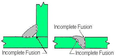
| Incomplete Fusion - A weld discontinuity in which fusion did not occur between weld metal and fusion faces or adjoining weld beads. |
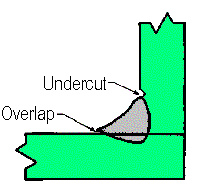
| Undercut - A groove melted into the base metal adjacent to the weld toe or weld root and left unfilled by weld metal. Overlap - The protrusion of weld metal beyond the weld toe or weld root. |
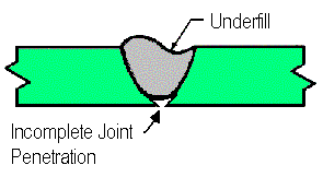
| Underfill - A condition in which the weld face or root surface extends below the adjacent surface of the base metal. Incomplete Joint Penetration - A joint root condition in a groove weld in which weld metal does not extend through the joint thickness |
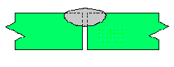
| Partial joint penetration groove welds are commonly specified in lowly loaded structures. However, incomplete joint penetration when a full penetration joint is required, as depicted above, would be cause for rejection. A fix for an incomplete penetration joint would be to back gouge and weld from the other side. Another acceptable partial penetration joint is shown below. | |
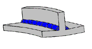
| Partial penetration joint on the left without discontinuities is an acceptable condition where appropriate. Appropriate engineering decisions need to be applied to determine what type of joint should be specified for a given application. |
Engineering should be contacted to determine whether partial penetration of full penetration joints are appropriate for a particular situation.
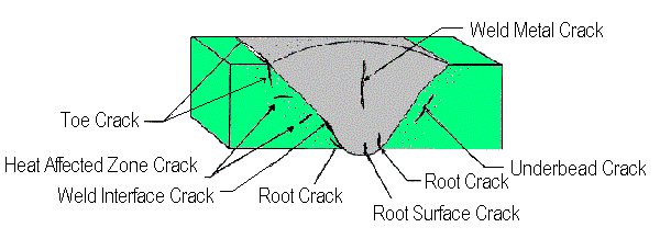
Above are several different representations of weld Cracking
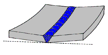
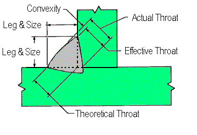
Below is a representation of a convex fillet weld without discontinuities.
If your company is experiencing these or other welding problems you can retain AMC to improve your weld processing. Hire AMC to act as your welding specialist.
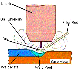
GTAW Welding
GTAW Welding
Common GTAW Welding ConcernsWe can help optimize your welding process variables. Evaluate your current welding parameters and techniques. Help eliminate common welding problems and discontinuities such as those listed below:
|