مهندسان جوش ( welding engineers )
جوشکاری یا عیبمهندسان جوش ( welding engineers )
جوشکاری یا عیبدرباره من
 با سلام خدمت تمام بازدید کنندگان
من بهزاد بهرامی بیرگانی دانشجوی
دانشگاه آزاد واحد شهر مجلسی
رشته مهندسی تکنولورژی جوشکاری
این وبلاگ صرفآ جهت افزایش اطلاعات
شما در این رشته جوشکاری جمع آوری
شده شما میتوانید با ثبت نظرات خود
من را آگاه کرده تا مطالب مورد نظر شما
را در صورت امکان در وبلاگ قرار داده تا
مورد استفاده بیشتر شما قرار گیرد
با تشکر از مهندس اسحق محمدی
برای کمک و رفع مشکلات شما به گروه
ما پیوست امیدوارم همیشه موفق باشد
بدورود .
با تشکر از یاسین غلامی زاده
مهندس و بازرس جوش
با ما در تماس باشید
ایمیل : welding.engineers@yahoo.com
مدیریت وبلاگ : بهزاد بهرامی بیرگانی
ادامه...
با سلام خدمت تمام بازدید کنندگان
من بهزاد بهرامی بیرگانی دانشجوی
دانشگاه آزاد واحد شهر مجلسی
رشته مهندسی تکنولورژی جوشکاری
این وبلاگ صرفآ جهت افزایش اطلاعات
شما در این رشته جوشکاری جمع آوری
شده شما میتوانید با ثبت نظرات خود
من را آگاه کرده تا مطالب مورد نظر شما
را در صورت امکان در وبلاگ قرار داده تا
مورد استفاده بیشتر شما قرار گیرد
با تشکر از مهندس اسحق محمدی
برای کمک و رفع مشکلات شما به گروه
ما پیوست امیدوارم همیشه موفق باشد
بدورود .
با تشکر از یاسین غلامی زاده
مهندس و بازرس جوش
با ما در تماس باشید
ایمیل : welding.engineers@yahoo.com
مدیریت وبلاگ : بهزاد بهرامی بیرگانی
ادامه...
دانلود پروژهای مهم


دانلود کتاب راهنمای جوش و اتصالات جوشی در ساختمانهای اسکلت فلزی

دانلود جزوه سازه های فولادی
جزوه سازه های فولادی - فولاد بعنوان ماده ای با مشخصات خاص و منحصر بفرد، مدتهاست در ساخت ساختمانها کاربرد دارد. قابلیت اجرای دقیق، رفتار سازه ای معین، نسبت مقاومت به وزن مناسب، در کنار امکان اجرای سریع سازه های فولادی همراه با جزئیات و ظرافتهای معماری ، فولاد را بعنوان مصالحی منحصر و ارزان در پروژه های ساختمانی مطرح نموده است؛ به نحوی که اگر ضعفهای محدود این ماده نظیر مقاومت کم در برابر خوردگی و عدم مقاومت در آتش سوزیهای شدید به درستی مورد توجه و کنترل قرار گیرند، امکانات وسیعی در اختیار طراح قرار می دهد که در هیچ ماده دیگر قابل دستیابی نیست.
فولاد و خواص آن
جوش
پیچ
قطعات کششی
قطعات فشاری
اتصالات
قطعات خمشی
تیر برق
صفحه ستون
مقاطع مختلط
اصطلاح فولاد یاپولاد برای آلیاژهای آهن که بین ۰/۰۲۵ تا حدود ۲ درصد کربن دارند بکار میرود فولادهای آلیاژی غالبا با فلزهای دیگری نیز همراهند. خواص فولاد به درصد کربن موجود در آن، عملیات حرارتی انجام شده بر روی آن و فلزهای آلیاژ دهنده موجود در آن بستگی دارد. از فولادی که تا ۰٫۲ درصد کربن دارد، برای ساختن سیم، لوله و ورق فولاد استفاده میشود. فولاد متوسط ۰٫۲ تا ۰٫۶ درصد کربن دارد و آن را برای ساختن ریل، دیگ بخار و قطعات ساختمانی بکار میبرند. فولادی که ۰٫۶ تا ۱٫۵ درصد کربن دارد، سخت است و از آن برای ساختن ابزارآلات، فنر و کارد و چنگال استفاده میشود. فولاد، انواع فراوانی دارد. که همه آن موراد در جدول کلید فولاد قایل دسترس می باشد.
بازرسی مخازن تحت فشار با استفاده از التراسونیک بروش
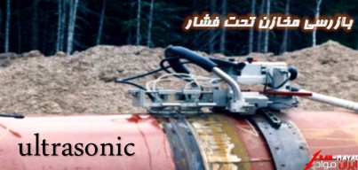
شرح :
تکنولوژی Phased Array ارائه دهنده یک مزیت تکنیکی در بازرسی جوش در مقایسه با روش قدیمی اولتراسونیک است. پرتو صوتی در Phased Array توانائی راهنمائی شدن ،اسکن کردن ، پیچ خوردن و متمرکز شدن را بصورت الکترونیکی دارد .توانایی راهنمائی شدن پرتو ، زاویه های پرتوهای انتخابی را بگونه ای هدایت می کند که در حین حرکت بصوت عمود به بعضی عیوب قابل پیش بینی برخورد کرده و آنها را نمایان سازد که این امر خصوصاً در مورد LOF قابل بیان است.
قالب بندی : PDF
تعداد صفحات :۱۲
حجم : ۰٫۷MB
 لینک دانلود
معرفی کدها و استانداردهای بازرسی تجهیزات مکانیکی در دوره بهره برداری، نگهداری و تعمیرات
مخازن، مبدلهای حرارتی، برج ها و بطور کلی ظروف تحت فشار مطابق الزامات کدها و استانداردهایی همچون کدهای آمریکایی ASME Sec VIII و کدهای اروپایی BS PD5500 طراحی و ساخته می شوند. این کدها در کنار الزامات طراحی و ساخت، الزامات تست و بازرسی را نیز شامل می شوند. پس از اینکه تجهیزات بازرسی نهایی شدند جهت نصب و راه اندازی به سایت ترخیص می شوند.
پس از نصب، تجهیزات آماده راه اندازی و در نهایت بهره برداری می گردند. در این مرحله یا دوره کدهای دیگری معرفی می شوند که الزامات مربوط به نگهداری و تعمیر تجهیزات با تمرکز بر بازرسی دوره ای آنها مطرح می شود. بطور نمونه می توان کد API 510 بعنوان کد بازرسی ظروف تحت فشار (بازرسی حین سرویس یا بهره برداری و تغییر ظرفیت و تعمیر ظروف تحت فشار) را نام برد.
همچنین استاندارد دیگری با عنوان API 572 (تکنیک های بازرسی ظروف تحت فشار) یا (API RP 572) برای بازرسی حین سرویس ظروف تحت فشار (یعنی در دوره بهره برداری) بسیار کاربردی و مفید می باشد. این استاندارد در واقع یک راهنمای توصیه شده است که در استانداردهای API با RP مشخص می شوند. RP به معنی Recommended Practice می باشد.
استانداردهای مرتبط با صنایع نفت ، گاز و پتروشیمی
| 1 | ANSI/AWS | A1.1-89 | Metric Practice Guide for the Welding Industry |
| 2 | ANSI/AWS | A2.4-98 | Standard Symbols for Welding, Brazing, and Nondestructive Examination |
| 3 | ANSI/AWS | A3.0-94 | Standard Welding Terms and Definitions |
| 4 | ANSI/AWS | A5.2-92 | Specification for Carbon and Low Alloy Steel Rods for Oxyfuel Gas Welding |
| 5 | ANSI/AWS | A5.01-93 | Filler Metal Procurement Guidelines |
| 6 | ANSI/AWS | A5.1-91 | Specification for Carbon Steel Electrodes for Shielded Metal Arc Welding |
| 7 | ANSI/AWS | A4.2-91 | Standard Procedures for Calibrating Magnetic Instruments to Measure the Delta Ferrite Content of Austenitic and Duplex Austenitic-Ferritic Stainless Steel Weld Metal |
| 8 | ANSI/AWS | A4.3-93 | Standard Methods for Determination of the Diffusible Hydrogen Content of Martensitic, Bainitic, and Ferritic Steel Weld Metal Produced by Arc Welding |
| 9 | ANSI/AWS | A5.6-84 | Specification for Covered Copper and Copper Alloy Arc Welding Electrodes |
| 10 | ANSI/AWS | A5.4-92 | Specification for Stainless steel Electrodes for Shielded Metal arc Welding |
| 11 | ANSI/AWS | A5.3-91 | Specification for Aluminum and Aluminum Alloy Electrodes for Shielded Metal Arc Welding |
| 12 | ANSI/AWS | A5.11-90 | Specification for Nickel and Nickel Alloy Welding Electrodes for Shielded Metal Arc Welding |
| 13 | ANSI/AWS | A5.12-92 | Specification for Tungsten and Tungsten Alloy Electrodes for Welding and Cutting |
| 14 | ANSI/AWS | A5.13-80 | Specification for Solid Surfacing Welding Rods and Electrodes |
| 15 | ANSI/AWS | A5.14/A5.14M-97 | Specification for Nickel and Nickel-Alloy Bare Welding Electrodes and Rods |
| 16 | ANSI/AWS | A5.9-93 | Specification for Bare Stainless Steel Welding Electrodes and Rods |
| 17 | ANSI/AWS | A5.10-92 | Specification for Bare Aluminum and Aluminum Alloy Welding Electrodes and Rods |
| 18 | ANSI/AWS | A5.8-92 | Specification for Filler Metals for Brazing and Braze Welding |
| 19 | ANSI/AWS | A5.7-84 | Specification for Copper and Copper Alloy Bare Welding Rods and Electrodes |
| 20 | ANSI/AWS | A5.18-93 | Specification for Carbon Steel Electrodes and Rods for Gas Shielded Arc Welding |
| 21 | ANSI/AWS | A5.17/A5.17M-97 | Specification for Carbon Steel Electrodes and Fluxes for Submerged Arc Welding |
| 22 | ANSI/AWS | A5.16-90 | Specification for Titanium and Titanium Alloy Welding Electrodes and Rods |
| 23 | ANSI/AWS | A5.15-90 | Specification for Welding Electrodes and Rods for Cast Iron |
| 24 | ANSI/AWS | A5.24-90 | Specification for Zirconium and Zirconium Alloy Welding Electrodes and Rods |
| 25 | ANSI/AWS | A9.1-92 | Standard Guide for Describing Arc Welds in Computerized Material Property and Nondestructive Examination Databases |
| 26 | ANSI/AWS | A5.19-92 | Specification for Magnesium alloy Welding Electrodes and Rods |
| 27 | ANSI/AWS | A5.32/A5.32M-97 | Specification for Welding Shielding Gases |
| 28 | ANSI/AWS | A5.31-92 | Specification for Fluxes for Brazing and Braze Welding |
| 29 | ANSI/AWS | A9.2-92 | Standard Guide for Recording Arc Weld Material Property and Nondestructive Examination Data in Computerized Databases |
| 30 | ANSI/AWS | A5.30-97 | Specification for Consumable Inserts |
| 31 | ANSI/AWS | A5.29-80 | Specification for Low Alloy Steel Electrodes for Flux Cored Arc Welding |
| 32 | ANSI/AWS | A5.26-91 | Specification for Carbon and Low Alloy Steel Electrodes for Electrogas Welding |
| 33 | ANSI/AWS | A5.25-91 | Specification for Carbon and Low Alloy Steel Electrodes and Fluxes for Electroslag Welding |
| 34 | ANSI/AWS | B2.1.005-90 | Standard Welding procedure specification (WPS) for gas metal arc welding of austenitic stainless steel (M-8 or P-8), 10 through 18 gage, in the as- welded condition, with or without backing |
| 35 | ANSI/AWS | B2.1-84 | Standard for welding procedure and performance qualification |
| 36 | ANSI/AWS | B1.10-86 | Guide for the Nondestructive inspection of welds |
| 37 | ANSI/AWS | B1.11-88 | Guide for the visual inspection of welds |
| 38 | ANSI/AWS | B2.1.001-90 | Standard Welding procedure specification (WPS) for Shielded metal arc welding of carbon steel, (M-1/P-1, group 1 or 2), 3/16 through 3/4 inch, in the As welded condition, with backing |
| 39 | ANSI/AWS | B2.1.003-90 | Standard Welding procedure specification (WPS) for Gas metal arc welding of galvanized steel, 10 through 18 gage, in the as-welded condition, with or without backing |
| 40 | ANSI/AWS | B2.1.004-90 | Standard Welding procedure specification (WPS) for Gas metal arc welding of carbon steel (M-1, Group 1), 10 through 18 gage, in the as-welded condition, with or without backing |
| 41 | ANSI/AWS | B2.1.002-90 | Standard Welding procedure specification (WPS) for Gas Tungsten Arc Welding of carbon Steel, (M-1/P-1, Group 1 or 2), 3/16 through 7/8 inch, in the as-welded condition, with or without backing |
| 42 | ANSI/AWS | B2.1.009-90 | Standard Welding procedure specification (WPS) for Gas Tungsten Arc Welding of austenitic stainless steel (M-8 or P-8), 10 through 18 gage, in the as- welded condition, with or without backing |
| 43 | ANSI/AWS | B2.1.008-90 | Standard Welding procedure specification (WPS) for Gas Tungsten Arc Welding of carbon steel, (M-1, group 1), 10 through 18 gage, in the as-welded condition, with or without backing |
| 44 | ANSI/AWS | B2.1.007-90 | Standard Welding procedure specification (WPS) for Gas Tungsten Arc Welding of galvanized steel, 10 through 18 gage, in the as-welded condition, with or without backing |
| 45 | ANSI/AWS | B2.1.006-90 | Standard Welding procedure specification (WPS) for Gas metal arc welding of carbon steel to austenitic stainless steel (M-1 to M-8 or P-8), 10 through 18 gage, in the as-welded condition, with or without backing |
| 46 | ANSI/AWS | B2.1.011-91 | Standard Welding procedure specification (WPS) for Shielded metal arc welding of galvanized steel, 10 through 18 gage, in the as-welded condition, with or without backing |
| 47 | ANSI/AWS | B2.1.012-91 | Standard Welding procedure specification (WPS) for Shielded metal arc welding of carbon steel (M-1, group 1), 10 through 18 gage, in the as-welded condition, with or without backing |
| 48 | ANSI/AWS | B2.1.013-91 | Standard Welding procedure specification (WPS) for Shielded metal arc welding of austenitic stainless steel (M-8/P-8), 10 through 18 gage, in the as-welded condition, with or without backing |
| 49 | ANSI/AWS | B2.1.010-90 | Standard Welding procedure specification (WPS) for Gas Tungsten Arc Welding of carbon steel to austenitic stainless steel (M-1 to M-8 or P-8), 10 through 18 gage, in the as-welded condition, with or without backing |
| 50 | ANSI/AWS | B2.1.015-91 | Standard Welding procedure specification (WPS) for Gas Tungsten Arc Welding of Aluminum,(M-22 or P-22), 10 through 18 gage, in the as-welded condition, with or without backing |
| 51 | ANSI/AWS | B2.1.014-91 | Standard Welding procedure specification (WPS) for Shielded metal arc welding of carbon steel to austenitic stainless steel (M-1 to M-8 or P-8), 10 through 18 gage, in the as-welded condition, with or without backing |
| 52 | ANSI/AWS | B2.1-8-023-94 | Standard Welding procedure specification (WPS) for Shielded metal arc welding of austenitic stainless steel (M-8/P-8/S-8, Group 1), 1/8 through 1-1/2 inch thick, As Welded Condition |
| 53 | ANSI/AWS | B2.2-91 | Standard for Brazing Procedure and Performance Qualification |
| 54 | ANSI/AWS | B2.1-8-025-94 | Standard Welding procedure specification (WPS) for Gas Tungsten Arc Welding followed by Shielded metal arc welding of austenitic stainless steel (M-8/P-8/S-8, Group 1), 1/8 through 1-1/2 inch thick, As Welded Condition |
| 55 | ANSI/AWS | B2.1-8-024-94 | Standard Welding procedure specification (WPS) for Gas Tungsten Arc Welding of austenitic stainless steel (M-8/P-8/S-8, Group 1), 1/8 through 1-1/2 inch thick, As Welded Condition |
| 56 | ANSI/AWS | B2.1-1-016-94 | Standard Welding procedure specification (WPS) for Shielded metal arc welding of carbon steel (M-1/P-1/S-1, Group 1 or 2), 1/8 through 1-1/2 inch thick, E7018, As Welded or PWHT Condition |
| 57 | ANSI/AWS | B4.0-92 | Standard Methods for Mechanical Testing of Welds |
| 58 | ANSI/AWS | B2.1-1-026-94 | Standard Welding procedure specification (WPS) for Shielded metal arc welding of carbon steel (M-1/P-1/S-1, Group 1 or 2), 1/8 through 1-1/2 inch thick, E6010(Vertical Downhill) Followed by E7018, As Welded or PWHT Condition |
| 59 | ANSI/AWS | B2.1-1-021-94 | Standard Welding procedure specification (WPS) for Gas Tungsten Arc Welding followed by Shielded metal arc welding of Carbon Steel (M-1/P-1/S-1, Group 1 or 2), 1/8 through 1-1/2 inch thick, ER70S-2 and E7018, As Welded or PWHT Condition |
| 60 | ANSI/AWS | B2.1-1-020-94 | Standard Welding procedure specification (WPS) for 75% Ar/25% CO2 Shielded Flux Cored Arc Welding of Carbon Steel (M-1/P-1/S-1, Group 1 or 2), 1/8 through 1-1/2 inch thick, E70T-1 and E71T-1, As Welded or PWHT Condition |
| 61 | ANSI/AWS | B2.1-1-022-94 | Standard Welding procedure specification (WPS) for Shielded metal arc welding of carbon steel (M-1/P-1/S-1, Group 1 or 2), 1/8 through 1-1/2 inch thick, E6010(Vertical Uphill) Followed by E7018, As Welded or PWHT Condition |
| 62 | ANSI/AWS | B2.1-1-027-95 | Standard Welding procedure specification (WPS) for Self-Shielded Flux Cored Arc Welding of Carbon Steel (M-1/P-1/S-1, Group 1 or 2), 1/8 through 3/4 inch thick, E71T-11, As Welded Condition |
| 63 | ANSI/AWS | B2.1-1-019-94 | Standard Welding procedure specification (WPS) for CO2 Shielded Flux Cored Arc welding of carbon steel (M-1/P-1/S-1, Group 1 or 2), 1/8 through 1-1/2 inch thick, E70T-1 and E71T-1, As Welded Condition |
| 64 | ANSI/AWS | B2.1-1-018-94 | Standard Welding procedure specification (WPS) for Self-Shielded Flux Cored Arc Welding of Carbon Steel (M-1/P-1/S-1, Group 1 or 2), 1/8 through 1-1/2 inch thick, E71T-8, As Welded Condition |
| 65 | ANSI/AWS | B2.1-1-017-94 | Standard Welding procedure specification (WPS) for Shielded metal arc welding of carbon steel (M-1/P-1/S-1, Group 1 or 2), 1/8 through 1-1/2 inch thick, E6010, As Welded or PWHT Condition |
| 66 | ANSI/AWS | B2.1-1-204-96 | Standard Welding procedure specification (WPS) for Shielded metal arc welding of carbon steel (M-1/P-1/S-1, Group 1 or 2), 1/8 through 3/4 inch thick, E6010(Vertical Downhill Root with the Balance Vertical Uphill), As Welded Condition, Primarily Pipe Applications |
| 67 | ANSI/AWS | B2.1-1-203-96 | Standard Welding procedure specification (WPS) for Shielded metal arc welding of carbon steel (M-1/P-1/S-1, Group 1 or 2), 1/8 through 3/4 inch thick, E6010(Vertical Uphill), As-Welded Condition, Primarily Pipe Applications |
| 68 | ANSI/AWS | B2.1-1-201-96 | Standard Welding procedure specification (WPS) for Shielded metal arc welding of carbon steel (M-1/P-1/S-1, Group 1 or 2), 1/8 through 3/4 inch thick, E6010(Vertical Uphill) Followed by E7018 (Vertical Uphill), As-Welded Condition, Primarily Pipe Applications |
| 69 | ANSI/AWS | B2.1-1-202-96 | Standard Welding procedure specification (WPS) for Shielded metal arc welding of carbon steel (M-1/P-1/S-1, Group 1 or 2), 1/8 through 3/4 inch thick, E6010(Vertical Downhill) Followed by E7018 (Vertical Uphill), As-Welded Condition, Primarily Pipe Applications |
| 70 | ANSI/AWS | B2.1-1-205-96 | Standard Welding procedure specification (WPS) for Shielded metal arc welding of carbon steel (M-1/P-1/S-1, Group 1 or 2), 1/8 through 1-1/2 inch thick, E6010(Vertical Uphill) Followed by E7018 (Vertical Uphill), As-Welded or PWHT Condition, Primarily Pipe Applications |
| 71 | ANSI/AWS | B2.1-1-208-96 | Standard Welding procedure specification (WPS) for Shielded metal arc welding of carbon steel (M-1/P-1/S-1, Group 1 or 2), 1/8 through 1-1/2 inch thick, E7018, As-Welded or PWHT Condition, Primarily Pipe Applications |
| 72 | ANSI/AWS | B2.1-1-206-96 | Standard Welding procedure specification (WPS) for Shielded metal arc welding of carbon steel (M-1/P-1/S-1, Group 1 or 2), 1/8 through 1-1/2 inch thick, E6010(Vertical Downhill) Followed by E7018 (Vertical Uphill), As-Welded or PWHT Condition, Primarily Pipe Applications |
| 73 | ANSI/AWS | B2.1-1-207-96 | Standard Welding procedure specification (WPS) for Gas Tungsten Arc welding of carbon steel (M-1/P-1/S-1, Group 1 or 2), 1/8 through 1-1/2 inch thick, ER70S-2, As-Welded or PWHT Condition, Primarily Pipe Applications |
| 74 | ANSI/AWS | B2.1-1-209-96 | Standard Welding procedure specification (WPS) for Gas Tungsten Arc welding Followed by Shielded Metal Arc Welding of Carbon Steel (M-1/P-1/S-1, Group 1 or 2), 1/8 through 1-1/2 inch thick, ER70S-2 and E7018, As-Welded or PWHT Condition, Primarily Pipe Applications |
| 75 | ANSI/AWS | B2.1-1-210-96 | Standard Welding procedure specification (WPS) for Gas Tungsten Arc welding with Consumable Inserts of carbon steel (M-1/P-1/S-1, Group 1 or 2), 1/8 through 1-1/2 inch thick, INMs-1 and ER70S-2, As-Welded or PWHT Condition, Primarily Pipe Applications |
| 76 | ANSI/AWS | B2.1-1-211-96 | Standard Welding procedure specification (WPS) for Gas Tungsten Arc welding with Consumable Inserts Followed by Shielded metal Arc Welding of carbon steel (M-1/P-1/S-1, Group 1 or 2), 1/8 through 1-1/2 inch thick, INMs-1, ER70S-2 and E7018, As-Welded or PWHT Condition, Primarily Pipe Applications |
| 77 | ANSI/AWS | C2.16-92 | Guide for Thermal-Spray Operator Qualification |
| 78 | ANSI/AWS | C1.1-66 | Recommended Practice for Resistance Welding |
| 79 | ANSI/AWS | C2.14-74 | Corrosion Tests of Flame-Sprayed Coated Steel, 19-Year Report |
| 80 | ANSI/AWS | C1.3-70 | Recommended Practices for Resistance Welding Coated Low Carbon Steels |
| 81 | ANSI/AWS | C2.2-67 | Recommended Practices for Metallizing with Aluminum and Zinc for Protection of Iron and Steel |
| 82 | ANSI/AWS | C2.18-93 | Guide for the Protection of Steel with Thermal Sprayed Coatings of Aluminum and Zinc and their Alloys and Composites |
| 83 | ANSI/AWS | C5.5-80 | Recommended Practices for Gas Tungsten Arc Welding |
| 84 | ANSI/AWS | C5.4-93 | Recommended Practices for Stud Welding |
| 85 | ANSI/AWS | C5.6-89 | Recommended Practices for Gas Metal Arc Welding |
| 86 | ANSI/AWS | C5.7-89 | Recommended Practices for Electrogas Welding |
| 87 | ANSI/AWS | C5.10-94 | Recommended Practices for Shielding Gases for Welding and Plasma Arc Cutting |
| 88 | ANSI/AWS | C4.2-90 | Operator's Manual for Oxyfuel Gas Cutting |
| 89 | ANSI/AWS | C4.3-83 | Operators Manual for Oxyfuel Gas Heating Torch Operation |
| 90 | ANSI/AWS | C5.3-91 | Recommended Practices for Air Carbon Arc Gouging and Cutting |
| 92 | ANSI/AWS | C5.1-73 | Recommended Practices for Plasma-Arc Welding |
| 93 | ANSI/AWS | C3.8-90 | Recommended Practices for Ultrasonic Inspection of Brazed Joints |
| 94 | ANSI/AWS | C3.3-80 | Recommended Practices for Design, Manufacture, and Inspection of Critical Brazed Components |
| 96 | ANSI/AWS | C6.1-89 | Recommended Practices for Friction Welding |
| 97 | ANSI/AWS | C3.2-82 | Standard Method for Evaluating the Strength of Brazed Joints in Shear |
| 98 | ANSI/AWS | C7.1-92 | Recommended Practices for Electron Beam Welding |
| 99 | ANSI/AWS | D8.7-88 | Recommended Practices for Automotive Weld Quality Resistance Spot Welding |
| 100 | ANSI/AWS | D10.4-86 | Recommended Practices for Welding Austenitic Chromium-Nickel Stainless Steel Piping and Tubing |
| 101 | ANSI/AWS | D8.8-89 | Specification for Automotive Frame Weld Quality Arc Welding |
| 102 | ANSI/AWS | D10.6-91 | Recommended Practices for Gas Tungsten Arc Welding of Titanium Pipe and Tubing |
| 103 | ANSI/AWS | D10.4-86 | Recommended Practices for Welding Austenitic Chromium-Nickel Stainless Steel Piping and Tubing |
| 104 | ANSI/AWS | D9.1-90 | Sheet Metal Welding Code |
| 105 | ANSI/AWS | D8.9-97 | Recommended Practices for Test Methods for Evaluating the Resistance Spot Welding Behavior of Automotive Sheet Steel Materials |
| 106 | ANSI/AWS | D3.5-93 | Guide for Steel Hull Welding |
| 107 | ANSI/AWS | D1.4-98 | Structural Welding Code Reinforcing Steel |
| 108 | ANSI/AWS | D1.3-89 | Structural Welding Code Sheet Steel |
| 109 | ANSI/AWS | D8.5-66 | Recommended Practices for Automotive Portable-Gun Resistance-Spot Welding on Electrode and Force Recommendations for Two and Three Loose Metal Thicknesses |
| 110 | ANSI/AWS | D3.6-93 | Specification for Underwater Welding |
| 111 | ANSI/AWS | D3.7-90 | Guide for Aluminum Hull Welding |
| 112 | ANSI/AWS | D1.2-90 | Structural Welding Code Aluminum |
| 113 | ANSI/AWS | D1.1-98 | Structural Welding Code Steel |
| 91 | ANSI/AWS | C5.2-83 | Recommended Practices for Plasma Arc Cutting |
| 95 | ANSI/AWS | C3.7-93 | Specification for Aluminum Brazing |
| 114 | ANSI/AWS | D10.12-89 | Recommended Practices and Procedures for Welding Low Carbon Steel Pipe |
| 115 | ANSI/AWS | D1.2A-83 | Commentary on Structural Welding Code Aluminum |
| 116 | ANSI/AWS | D10.11-87 | Recommended Practices for Root Pass Welding of Pipe Without Backing |
| 117 | ANSI/AWS | D10.10-90 | Recommended Practices for Local Heating of Welds in Piping and Tubing |
| 118 | ANSI/AWS | D10.7-86 | Recommended Practices for Gas Shielded Arc Welding of Aluminum and Aluminum Alloy Pipe |
| 119 | ANSI/AWS | D14.1-85 | Specification for Welding of Industrial and Mill Cranes and Others Material Handling Equipment |
| 121 | ANSI/AWS | D14.2-93 | Specification for Metal Cutting Machine Tool Weldments |
| 122 | ANSI/AWS | D14.4-77 | Classification and Application of Welded Joints for Machinery and Equipment |
| 123 | ANSI/AWS | D14.3-94 | Specification for Welding Earthmoving and Construction Equipment |
| 124 | ANSI/AWS | D14.5-97 | Specification for Welding of Processes and Press Components |
| 125 | ANSI/AWS | D14.6-96 | Specification for Welding of Rotating Elements of Equipment |
| 126 | ANSI/AWS | D11.2-89 | Guide for Welding Iron Castings |
| 127 | ASTM | A 193/A 193M – 01b | Standard Specification for Alloy-Steel and Stainless Steel Bolting Materials for High Temperature Service |
| 128 | ASTM | A 234 | Standard Specification for Piping Fittings of Wrought Carbon Steel and Alloy Steel for Moderate and High Temperature Service |
| 129 | ASTM | A 194 | Standard Specification for Carbon and Alloy Steel Nuts for Bolts for High Pressure or High Temperature Service, or Both |
| 130 | ASTM | A 192 | Standard Specification for Seamless Carbon Steel Boiler Tubes for High-Pressure Service |
| 131 | ASTM | A 106 | Standard Specification for Seamless Carbon Steel Pipe for High-Temperature Service |
| 132 | ASTM | A 182 | Standard Specification for Forged or Rolled Alloy-Steel Pipe Flanges, Forged Fittings, and Valves and Parts for High-Temperature Service |
| 133 | ASTM | A 181 | Standard Specification for Carbon Steel Forgings, for General-Purpose Piping |
| 134 | ASTM | A 53 | Standard Specification for Pipe, Steel, Black and Hot-Dipped, Zinc-Coated, Welded and Seamless |
| 135 | ASTM | A 105 | Standard Specification for Carbon Steel Forgings for Piping Applications |
| 136 | ASTM | A 20 | Standard Specification for General Requirements for Steel Plates for Pressure Vessels |
| 137 | ASTM | A 36 | Standard Specification for Carbon Structural Steel |
| 138 | ASTM | A 6 | Standard Specification for General Requirements for Rolled Structural Steel Bars, Plates, Shapes, and Sheet Piling |
| 139 | API | 5L-2000 | Specification for Line Pipe |
| 140 | API | 5B-96 | Specification for Threading, Gauging, and Thread Inspection of Casing, Tubing, and Line Pipe Threads (U.S. Customary Units) |
| 141 | ASTM | A 517 | Standard Specification for Pressure Vessel Plates, Alloy Steel, High-Strength, Quenched and Tempered |
| 142 | ASTM | A 435 | Standard Specification for Straight-Beam Ultrasonic Examination of Steel plates |
| 143 | ASTM | A 333 | Standard Specification for Seamless and Welded Steel Pipe for Low-Temperature Service |
| 144 | ASTM | A 516 | Standard Specification for Pressure Vessel Plates, Carbon Steel, for Moderate- and Lower-Temperature Service |
| 145 | ASTM | A 479 | Standard Specification for Stainless Steel Bars and Shapes for Use in Boilers and Other Pressure Vessels |
| 146 | ASTM | A 312 | Standard Specification for Seamless and Welded Austenitic Stainless Steel Pipes |
| 147 | ASTM | A 320 | Standard Specification for Alloy/Steel Bolting Materials for Low-Temperature Service |
| 148 | ASTM | A 285 | Standard Specification for Pressure Vessel Plates, Carbon Steel, Low- and Intermediate-Tensile Strength |
| 149 | ASTM | A 299 | Standard Specification for Pressure Vessel Plates, Carbon Steel, Manganese-Silicon |
| 150 | ASTM | A 240 | Standard Specification for Heat-Resisting Chromium and Chromium-Nickel Stainless Steel Plate, Sheet, and Strip for Pressure Vessels |
| 151 | ASTM | A 283 | Standard Specification for Low and Intermediate Tensile Strength Carbon Steel Plates |
| 152 | ASTM | A 234 | Standard Specification for Piping Fittings of Wrought Carbon Steel and Alloy Steel for Moderate and High Temperature Service |
| 153 | ASTM | A 694 | Standard Specification for Carbon and Alloy Steel Forgings for Pipe Flanges, Fittings, Valves, and Parts for High-Pressure Transmission Service |
| 154 | ASTM | A 573 | Standard Specification for Structural Carbon Steel Plates of Improved Toughness |
| 155 | ASTM | A 563 | Standard Specification for Carbon and Alloy Steel Nuts |
| 156 | ASTM | A 537 | Standard Specification for Pressure Vessel Plates, Heat-Treated, Carbon-Manganese-Silicon Steel |
| 157 | API | 675-94 | Positive Displacement Pumps Controlled Volume |
| 158 | API | 650-98 | Welded Steel Tanks for Oil Storage |
| 159 | API | 1104-99 | Welding of Pipelines and Related Facilities |
| 160 | API | 6D-94 | Specification for Pipeline Valves (Gate, Ball, and Check Valves) |
| 161 | API | 620-98 | Design and Construction of Large, Welded, Low-Pressure Storage Tanks |
| 162 | API | RP 520-93 | Sizing, Selection, and Installation of Pressure-Relieving Devices in Refineries - part 1 |
| 163 | API | 17D-92 | Specification for Subsea Wellhead and Christmas Tree Equipment |
| 164 | API | RP 520-93 | Sizing, Selection, and Installation of Pressure-Relieving Devices in Refineries - part 2 |
| 165 | API | 6A-99 | Specification for Wellhead and Christmas Tree Equipment |
| 166 | API | 598-96 | Valve Inspection and Testing |
| 167 | ASME/ANSI | B18.2.2-87 | Square and Hex Nuts(Inch Series) |
| 168 | ASME/ANSI | B18.2.1a-99 | Addenda to ASME B18.2.1-96 Square and Hex Bolts and Screws (Inch Series) |
| 169 | ASME/ANSI | B31.8-99 | Gas Transmission and Distribution Piping Systems |
| 170 | ASME/ANSI | B31.4-98 | Pipeline Transportation Systems for Liquid Hydrocarbons and Other Liquids |
| 171 | ASME/ANSI | B31.3a-2000 | Addenda to ASME B31.3-99 Process Piping |
| 172 | ASME/ANSI | B31G-91 | Manual for Determining the Remaining Strength of Corroded Pipelines |
| 173 | ASME/ANSI | B16.5a-1998 | Addenda to ASME B16.5-1996 PIPE FLANGES AND FLANGED FITTINGS NPS 1/2 Through NPS 24 |
| 174 | ASME/ANSI | B16.9-93 | Factory-Made Wrought Steel Buttwelding Fittings |
| 175 | ASME/ANSI | B16.25-97 | Buttwelding Ends |
| 176 | ASME/ANSI | B16.34a-1998 | Addenda to ASME B16.34-1996 VALVES - FLANGED, THREADED, AND WELDING END |
| 177 | ASME/ANSI | B16.11-96 | Forged Fittings, Socket-Welding and Threaded |
| 178 | NACE | RP0177-2000 | Standard Recommended Practice Mitigation of Alternating Current and Lightning Effects on Metallic Structures and Corrosion Control Systems |
| 179 | NACE | MR0175-2002 | Standard Material Requirements Sulfide Stress Cracking Resistant Metallic Materials for Oilfield Equipment |
| 180 | NACE | RP0169-96 | Standard Recommended Practice Control of External Corrosion on Underground or Submerged Metallic Piping Systems |
| 181 | NACE | RP0170-97 | Standard Recommended Practice Protection of Austenitic Stainless Steels and Other Austenitic Alloys from Polythionic Acid Stress Corrosion Cracking During Shutdown of Refinery Equipment |
| 182 | NACE | RP0176-94 | Standard Recommended Practice Corrosion Control of Steel Fixed Offshore Platforms Associated with Petroleum Production |
| 183 | MSS | SP-44 | Steel Pipeline Flanges |
| 184 | MSS | SP-58 | Pipe Hangers and Supports Materials, Design and Manufacture |
| 185 | MSS | SP-53 | Quality Standard for Steel Castings and Forgings for Valves, Flanges and Fittings and other Piping Components - Magnetic Particle Examination Method |
| 186 | MSS | SP-55 | Quality Standard for Steel Castings for Valves, Flanges and Fittings and Other Piping Components Visual Method |
| 187 | MSS | SP-25-1993 | Standard Marking System for Valves, Fittings, Flanges and Unions |
| 188 | MSS | SP-42 | Class 150 Corrosion Resistant Gate, Globe, Angle and Check Valves with Flanged and Butt Weld Ends |
| 189 | MSS | SP-43 | Wrought Stainless Steel Butt-Welding Fittings |
| 190 | MSS | SP-45 | Bypass and Drain Connections |
| 191 | MSS | SP-51 | Class 150 LW Corrosion Resistant Cast Flanges and Flanged Fittings |
| 192 | MSS | SP-53 | Quality Standard for Steel Castings and Forgings for Valves, Flanges, and Fittings and Other Piping Components — Magnetic Particle Examination Method |
| 193 | MSS | SP-54 | Quality Standard for Steel Castings for Valves, Flanges and Fittings and Other Piping Components — Radiographic Examination Method |
| 194 | MSS | SP-58 | Pipe Hangers and Supports — Materials, Design and Manufacture |
| 195 | MSS | SP-60 | Connecting Flange Joint Between Tapping Sleeves and Tapping Valves |
| 196 | MSS | SP-61 | Pressure Testing of Steel Valves |
| 197 | MSS | SP-65 | High Pressure Chemical Industry Flanges and Threaded Stubs for Use with Lens Gaskets |
| 198 | MSS | SP-67 | Butterfly Valves |
| 199 | MSS | SP-70 | Cast Iron Gate Valves, Flanged and Threaded Ends |
| 200 | MSS | SP-72 | Ball Valves with Flanged or Butt-Welding Ends for General Service |
| 201 | MSS | SP-75 | Specifications for High Test Wrought Butt Welding Fittings |
| 202 | MSS | SP-77 | Guidelines for Pipe Support Contractual Relationships |
| 203 | MSS | SP-78 | Cast Iron Plug Valves, Flanged and Threaded Ends |
| 204 | MSS | SP-79 | Socket-Welding Reducer Inserts |
| 205 | MSS | SP-81 | Stainless Steel, Bonnetless, Flanged Knife Gate Valves |
| 206 | MSS | SP-82 | Valve Pressure Testing Methods |
| 207 | MSS | SP-83 | Steel Pipe Unions, Socket-Welding and Threaded |
| 208 | MSS | SP-85 | Cast Iron Globe & Angle Valves, Flanged and Threaded Ends |
| 209 | MSS | SP-87 | Factory-Made Butt-Welding Fittings for Class I Nuclear Piping Applications |
| 210 | MSS | SP-88 | Diaphragm Type Valves |
| 211 | MSS | SP-90 | Guidelines on Terminology for Pipe Hangers and Supports |
| 212 | MSS | SP-91 | Guidelines for Manual Operation of Valves |
| 213 | MSS | SP-92 | MSS Valve User Guide |
| 214 | MSS | SP-93 | Quality Standard for Steel Castings and Forgings for Valves, Flanges, and Fittings and Other Piping Components — Liquid Penetrant Examination Method |
| 215 | MSS | SP-94 | Quality Standard for Ferritic and Martensitic Steel Castings for Valves, Flanges, and Fittings and Other Piping Components — Ultrasonic Examination Method |
| 216 | MSS | SP-95 | Swage(d) Nipples and Bull Plugs |
| 217 | MSS | SP-97 | Forged Carbon Steel Branch Outlet Fittings — Socket Welding, Threaded and Buttwelding Ends |
| 218 | MSS | SP-99 | Instrument Valves |
| 219 | MSS | SP-101 | Part-Turn Valve Actuator Attachment— Flange and Driving Component Dimensions and Performance Characteristics |
| 220 | MSS | SP-102 | Multi-Turn Valve Actuator Attachment — Flange and Driving Component Dimensions and Performance Characteristics |
| 221 | MSS | SP-103 | Wrought Copper and Copper Alloy Insert Fittings for Polybutylene Systems |
| 222 | MSS | SP-104 | Wrought Copper Solder Joint Pressure Fittings |
| 223 | MSS | SP-105 | Instrument Valves for Code Applications |
| 224 | MSS | SP-106 | Cast Copper Alloy Flanges and Flanged Fittings, Class 125, 150 and 300 |
| 225 | MSS | SP-107 | Transition Union Fittings for Joining Metal and Plastic Products |
| 226 | MSS | SP-108 | Resilient Seated-Eccentric Cast Iron Plug Valves |
| 227 | MSS | SP-112 | Quality Standard for Evaluation of Cast Surface Finishes — Visual and Tactile Method. This SP must be sold with a 10-surface, three-dimensional Cast Surface Comparator, which is a necessary part of the Standard. Additional comparators may be sold separately. |
| 228 | MSS | SP-113 | Connecting Joint between Tapping Machines and Tapping Valves |
| 229 | MSS | SP-114 | Corrosion Resistant Pipe Fittings Threaded and Socket Welding Class 150 and 1000 |
| 230 | MSS | SP-115 | Excess Flow Valves for Natural Gas Service |
| 231 | MSS | SP-60 | Connecting Flange Joint between Tapping Sleeves and Tapping Valves |
| 232 | MSS | SP-91 | Guidelines for Manual Operation of Valves |
| 233 | MSS | SP-93 | Quality Standard for Steel Castings and Forgings for Valves, Flanges, and Fittings and Other Piping Components — Liquid Penetrant Examination Method |
| 234 | ASME | A13.1 | SCHEME FOR THE IDENTIFICATION OF PIPING SYSTEMS |
| 235 | ASME | B1.16M | Gages and Gaging for Metric M Screw Threads |
| 236 | ASME | B1.15 | Unified Inch Screw Threads (UNJ Thread Form) |
| 237 | ASME | B1.20.1 | PIPE THREADS, GENERAL PURPOSE (INCH) |
| 238 | ASME | A13.1 | SCHEME FOR THE IDENTIFICATION OF PIPING SYSTEMS |
| 239 | ASME | B1.3M | Screw Thread Gaging Systems for Dimensional Acceptability - Inch and Metric Screw Threads (UN, UNR, UNJ, M, and MJ) |
| 120 | ANSI/AWS | D10.13-95 | Recommended Practices for the Brazing of Copper Pipe and Tubing for Medical Gas Systems |
| 240 | ASME | B1.7M | Nomenclature, Definitions, and Letter Symbols for Screw Threads |
| 241 | ASME | B1.2 | Gages and Gaging for Unified Inch Screw Threads |
| 242 | ASME | B1.1 | Unified Inch Screw Threads (UN and UNR Thread Form) |
| 243 | ASME | NQA-1 - 1997 | QUALITY ASSURANCE REQUIREMENTS FOR NUCLEAR FACILITY APPLICATIONS |
| 244 | ASME | B1.20.3 | Dryseal Pipe Threads (Inch) |
| 245 | ASME | AS-11 | Personnel of Codes, Standards, and Related Accreditation Registration, and Certification Committees |
| 246 | ASME | B16.11-1996 | FORGED FITTINGS, SOCKET-WELDING AND THREADED |
| 247 | ASME | B1.20.5 | GAGING FOR DRYSEAL PIPE THREADS (INCH) |
| 248 | ASME | B16.12 | Cast Iron Threaded Drainage Fittings |
| 249 | ASME | B16.10 | Face-to-Face and End-to-End Dimensions of Valves |
| 250 | ASME | B16.9 | Factory-Made Wrought Steel Buttwelding Fittings |
| 251 | ASME | B16.4 | Cast Iron Threaded Fittings |
| 252 | ASME | B16.1 | Cast Iron Pipe Flanges and Flanged Fittings |
| 253 | ASME | B4.2 | Preferred Metric Limits and Fits |
| 254 | ASME | B16.3 | Malleable Iron Threaded Fittings |
| 255 | ASME | B1.22M | Gages and Gaging for MJ Series Metric Screw Threads |
| 256 | ASME | B1.21M | METRIC SCREW THREADS: MJ PROFILE |
| 257 | ASME | B1.20.7 | HOSE COUPLING SCREW THREADS (INCH) |
| 258 | ASME | Y14.36M | SURFACE TEXTURE SYMBOLS |
| 259 | ASME | Y14.5M | Dimensioning and Tolerancing |
| 260 | ASME | Y14.5.1M | Mathematical Definition of Dimensioning and Tolerancing Principles |
| 261 | ASME | SPPE-2 | Accreditation of Testing Laboratories for Safety and Pollution Prevention Equipment Used in Offshore Oil and Gas Operations |
| 262 | ASME | PTC 25 | Pressure Relief Devices |
| 263 | ASME | PTC 19.2 | PART 2: Pressure Measurement INSTRUMENTS AND APPARATUS |
| 264 | ASME | B31G | Manual for Determining the Remaining Strength of Corroded Pipelines |
مراحل ساخت مخازن ذخیره
جوشکاری صحیح و مناسب مخازن ذخیره از اهمیت ویژه ای برخوردار است چرا که یک مشکل جزئی در محل اتصال اجزا این مخازن در هنگام استفاده و بهره برداری می تواند باعث هدررفتن سرمایه و سلب امنیت گردد. لذا کنترل کیفیت و بازرسی ساخت این مخازن بایستی مورد توجه قرار گیرد اگر نکات ویژه مربوط به ساخت مخازن به درستی بکار گرفته نشود مخزن ساخته شده علاوه بر نمای ظاهری نامطلوب دارای کیفیت پایینی بوده و عمر بهره برداری کوتاهی خواهد داشت.
ادامه مطلب ...
انواع مخازن ذخیره
مخازن جهت نگهداری و ذخیره سازی شاره ها مورد استفاده قرار می گیرند. بطور کلی مخازن بر اساس موارد زیر طبقه بندی می شوند :
۱- ماهیت ماده ای که بایستی در آن ذخیره شود.
بر این اساس مخازن به سه نوع مخازن نگهداری مواد در فشار محیط - مخازن نگهداری با فشار متوسط و مخازن نگهداری شاره ها با فشار پایین طبقه بندی می شوند.
۲- دمای کاری
بر این اساس مخازن به دو دسته مخازن نگهداری در دمای محیط و مخازن نگهداری در دماهای پایین دسته بندی می گردند.
۳- نوع سازه مخازن
در این نوع دسته بندی مخازن به چند دسته بالای سطح زمین - زیر سطح زمین و دو دیواره تقسیم بندی می شوند.
بطور کلی طراحیهای اصلی مورد استفاده در ساخت مخازن ذخیره را می توان به چهار گروه تقسیم بندی نمود :
۱- مخازن با سقف ثابت. سقف این مخازن جزء ساده ترین نوع مخازن می باشند و اکثر دوستان با این نوع مخازن سرو کار داشته اند. سقف این مخازن در جهت افقی و عمودی بدون حرکت می باشند.
۲- مخازن ذخیره با سقف شناور خارجی.
۳- مخازن ذخیره با سقف شناور داخلی.
۴- مخازن ذخیره سقف شناور با پوشش سقف گنبدی
۵- مخازن ذخیره با فشار متوسط
ادامه مطلب ...
WPS ( Welding Procedure Specification
جوشکاری (عملیات اتصالات) لوله های پلی اتیلن
فصل اول :
جوشکاری (عملیات اتصالات) لوله های پلی اتیلن
فهرست مطالب :
1- آماده سازی لوله های پلی اتیلن قبل از جوشکاری (عملیات اتصال)
2- جوشکاری و ارزیابی آنها
3- آماده نمودن سرلوله ها برای جوشکاری
4- جوشکاری (عملیات اتصال)
5- روش های جوشکاری
1-آماده سازی لوله های پلی اتیلن قبل از عملیات جوشکاری
آماده سازی لوله ها شامل بازرسی ، تمیزکاری و برش لوله ها قبل از جوشکاری می باشد.
1-1- بازرسی لوله ها
هر شاخه لوله قبل از آماده سازی باید بازرسی گردد لوله هایی که دارای هر نوع عیب از قبیل کج بودن، دوپهن بودن دهانه برآمدگی شیار، فرورفتگی، خراش و حفره باشند بایستی کنار گذارده شوند تا توسط مهندس یا نماینده او در صورت لزوم مهندس بازرسی شرکت ملی گاز بررسی و دستور وارده شدن، تعمیر ویا برش آنها جهت از بین بردن نقص داده شود.
قبل از جوشکاری لوله ها به یکدیگر بایستی اطمینان حاصل نمود که لوله ها عاری از هر گونه خاک و اشیاء خارجی می باشد.
2-1- تمیز کردن لبه لوله ها
قبل از اتصال لوله ها بایستی سطوح داخلی و خارجی آنها با وسایل مناسب از خاک و سایر مواد خارجی تمیز شود.
3-1 برش لوله ها
برش لوله بایستی توسط وسایل مخصوص برش که مورد تأیید مهندس یا بازرس می باشد انجام گیرد. مقطع بریده شده عمود بر محور طولی لوله باشد . برش فارسی یر (MITER ) جهت لوله و اتصالات مجاز نمی باشد.
4-1 جهت و انحراف لوله
1-4-1-کمانی شدن لوله
کمانی شدن لوله برای تغییر جهت مجاز خواهد بود، شعاع کمانی شدن بصورت ظریبیاز قطر لوله بوده که با در نظر گرفتن پشنهادات سازنده آن توسط مهندس یا نماینده او تعیین می گردد و باید بصورتی انجام شود که دچار چین و چروک نگردیده و دوپهن نشود.
هرگاه چنین نواقصی ایجاد گردد لوله وازده خواهد شد. در صورتیکه خم با شعاعهای خیلی کوچک مورد نظر باشد می بایستاز خمهای پیش ساخته در کارخانه استفاده نمود.
5-1- لوله های وازده شده
لوله های وازده شده بایستی با علامت (وازده) که بر روی آنها با رنگ رمز نوشته می شود مشخص گردند. اینگونه لوله ها بایستی بلافاصله از محل کار خارج شده و در انبار مخصوص وازده نگهداری شوند.
مقاله جامع در مورد جوشکاری لوله های پلی اتیلن
عیوب به وجود آمده در جوشکاری زیر پودری
Foxit Reader نرم افزاری برای مطالعه اسناد PDF + دانلود
با نرم افزار Foxit Reader می توانید فایل های PDF را باز کنید، پرینت بگیرید و یا آن ها را ویرایش کنید. از اینجا هم می توانید آخرین نسخه این برنامه را دانلود کنید.
به گزارش دریچه فناوری اطلاعات؛ امروزه بیشتر مقالات و کتاب های الکترونیک از فرمت محبوب و رایج PDF استفاده می کنند. دریچه فناوری اطلاعات اینجا برنامه مفید و کاربردی Foxit Reader را معرفی می کند. نرم افزار Foxit Reader به شما امکان باز کردن، مشاهده و پرینت هرگونه فایل پی دی اف را می دهد. این نرم افزار امکاناتی همچون زوم بر روی نوشته ها، جستجوی کلمات خاص، گرفتن پرینت از متن، تنظیمات مربوط به نمایش و بسیاری از ابزارهای متنوع دیگر را در اختیار شما قرار می دهد. در این نرم افزار ابزارهای متفاوتی قرار دارد ابزارهایی که با کمک آنها می توانید فایل های PDF مورد نظرتان را ویرایش نمایید.
